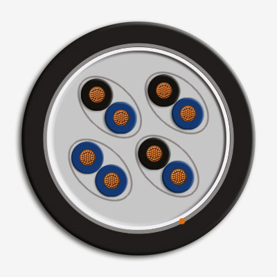
TRATOS® PAS 5308 Part 2/Type 1 – Unarmoured Construction

Control and Instrumentation cable
Publicly Available Specification PAS 5308-2 replaces BS 5308-2 and provides additional aspects not covered in the European standard for control and instrumentation cables, BS EN 50288-7. As the actual manufacturer of these cables, not simply a distributor, Tratos has total control of the design, quality and manufacturing process from the purchase of the raw materials through to final testing and despatch to our customers. Having control of the manufacturing process Tratos can ensure compatibility with most makes and types of glands. Tratos manufacture a complete range of control and instrumentation cables for industrial applications. Tratos control and instrumentation cables are available with either Class 2 or, to aid installation and allow repeated removal of meters for calibration, Class 5 conductors. Tratos control and instrumentation cables are available with individual or collective screens to confine the electric field and to limit the external electrical influences. In the Publicly Available Specification, cables are designated according to their construction, type 1 cables are unarmoured, type 2 cables have a single wire armour. Both types of cable have a PVC outer sheath.
Electric cables used for the supply of electricity and for control and communication purposes, which are intended for use in buildings and other civil engineering construction works are covered by the Construction Products Regulation No. 305/2011 and subject to performance requirements on reaction to fire.
Tratos control and instrumentation cables are available as class Cca (BS EN 50575) as standard, higher classifications are available on request
The ranges of control and instrumentation cables have been rationalised to preclude certain cable types and conductor sizes in accordance with current industry practice.
STANDARDS
- PAS 5038-2 – Design
- BS EN 60288 class 2 or class 5 – Conductor
- BS EN 50290-2-21 – Insulation
- BS EN 50290-2-22 – Sheath
Where CPR applies
- BS EN 50575
- CPR BS EN 13501-6
Where CPR does not apply
- IEC 60332-1 – Flame Retardant
- IEC60332-3-22 – Flame retardant

Contact us:
Tel: +44 20 3148 5178
e-mail: [email protected]
Please don’t hesitate to contact us if you need additional information about our products.
Application
Used for wiring control, protection, signalling, communication and data transmission circuits in industrial applications where individual or collective screening of the pairs by an earthed metallic layer to prevent cross talk and reduce external electrical influences is required. Type 1 control and instrumentation cables are unarmoured and therefore unsuitable for underground burial.CoONSTRUCTION
- Conductor: BS EN 60228 class 2 or class 5 plain annealed copper
- Insulation: Grade TI51 PVC to BS EN 50290-2-21
- Individual pair screen (optional)
- a) Aluminium/polyester tape, metallic side down, in contact with minimum 0.5mm2 tinned copper drain wire
- b) Polyester isolating tape(s) numbered for identification
- Tape: Polyester binder tape
- Collective screen (optional) - Aluminium/polyester tape, metallic side down, in contact with minimum 0.5mm2 tinned copper drain wire
- Outer sheath: Grade TM51 PVC to BS EN 50290-2-22
- Standard colour: Black (other colours available on request)
Standards
Technical Specifications
- Control and Instrumentation
- Rated voltage 150/250 V
- Maximum continuous conductor operating temperature for PVC insulation 65 °C.
- Minimum installation temperatures 0 °C.
- Minimum operation temperature when installed – 15 °C
- Provided not subject to movement or impact
Maximum DC Conductor resistance at 20 °C
- 0.5 mm2 / class 5 / 39.7 Ω/km
- 0.75 mm2 / class 5 / 26.5 Ω/km
- 1.5 mm2 / class 2 / 12.3 Ω/km
- 2.5 mm2 / class 2 / 7.6 Ω/km
Mutual capacitance
The mutual capacitance of the pairs or adjacent cores shall not exceed a maximum of 250 pf/m at a frequency of 1 kHz.
Capacitance between any core and core screen
The capacitance between any core and all other cores connected to any other metallic elements present (e.g. screens and armour) and earth shall not exceed 450 pF/m at a frequency of 1 kHz.
Inductance (L) to resistance (R) ratio
The L/R ratio for adjacent cores shall not exceed the values below.
L/R ratios for adjacent cores
Nominal cross-sectional area of conductor mm2/ Maximum UR ratio µH/Ω
- 0.5 / 25
- 0.75 / 25
- 1.5 / 40
- 2.5 / 60
Minimum bending radius
Type 2 cables 6D
Contact us
Please, don’t hesitate to contact us for additional information on our company or our products.
Other News
-
Tratos Celebrates a Successful Showcase at Middle East Energy 2025
-
Tratos participates in the UKEF Supplier Fair on Cabinda International Airport
-
Strategic Growth in Fibre Optic Technology for Tratos
-
Tratos Cavi Wins BTOB Award for Innovation
-
Egidio Capaccini Award 2024 edition
-
Tratos Cavi acquires AFL Telecommunications GmbH's German Plant
-
Tratos Visits CEECATL-China
-
Tratos Group Leaders Participated in ROG.e 2024 in Brazil


